- Главная
- Разное
- Бизнес и предпринимательство
- Образование
- Развлечения
- Государство
- Спорт
- Графика
- Культурология
- Еда и кулинария
- Лингвистика
- Религиоведение
- Черчение
- Физкультура
- ИЗО
- Психология
- Социология
- Английский язык
- Астрономия
- Алгебра
- Биология
- География
- Геометрия
- Детские презентации
- Информатика
- История
- Литература
- Маркетинг
- Математика
- Медицина
- Менеджмент
- Музыка
- МХК
- Немецкий язык
- ОБЖ
- Обществознание
- Окружающий мир
- Педагогика
- Русский язык
- Технология
- Физика
- Философия
- Химия
- Шаблоны, картинки для презентаций
- Экология
- Экономика
- Юриспруденция
Что такое findslide.org?
FindSlide.org - это сайт презентаций, докладов, шаблонов в формате PowerPoint.
Обратная связь
Email: Нажмите что бы посмотреть
Презентация на тему Currents in мetals
Содержание
- 2. Lecture 11Currents in MetalsThe effects of magnetic fields. The production and properties of magnetic fields.
- 3. Types of ConductivityConductors are materials through which
- 4. Drift speed of electronsThere is a zigzag
- 5. So when we consider electric current as
- 6. Current in metalsEvery atom in the metallic
- 7. ResistivityA conductor with current:Current density:I – electric
- 8. ConductivityA current density J and an electric
- 9. Ohm’s law againFor many materials (including most
- 10. MagnetsA single magnetic pole has never been
- 11. Magnet PolesMagnet field lines connect unlike poles.Magnet field lines repels from like poles.
- 12. Magnet ForceThe magnitude FB of the magnetic
- 13. The text in the previous slide can
- 14. Direction of FBRight hand rule: The fingers point
- 15. Magnetic field directionMagnetic field lines coming out
- 16. Magnetic Force on a CurrentMagnetic force is
- 17. n is the number density of charged
- 18. Arbitrary shaped wireThe force on a small
- 19. as B is uniform:The magnetic force on
- 20. So, the force on a straight wire
- 21. Loop Wire in a Uniform Magnetic fieldThe
- 22. Current Loop Torque in a Uniform Magnetic
- 23. When the magnetic field is parallel to
- 24. When the loop is not parallel to
- 25. In formula for torque we have
- 26. Right – hand rule for loop The direction of
- 27. Magnetic MomentThe vector product IA is defined
- 28. Potential Energy of a Magnetic MomentThe potential
- 29. Motion of a Charged Particle in a
- 30. Using the obtained formula we get the angular velocityhere v is perpendicular to B.
- 31. Lorentz ForceIn the presence of E and
- 32. The Hall EffectWhen a current-carrying conductor is
- 33. the magnetic force
- 34. Using that A=td – cross sectional area
- 35. When the charge carriers in a Hall-effect
- 36. Скачать презентацию
- 37. Похожие презентации
Lecture 11Currents in MetalsThe effects of magnetic fields. The production and properties of magnetic fields.











Слайд 3
Types of Conductivity
Conductors are materials through which charge
moves easily.
Insulators are materials through which charge does
not move easily. Semiconductors are materials intermediate to conductors and insulators.
Слайд 4
Drift speed of electrons
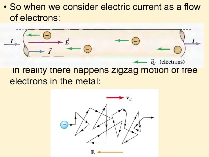
There is a zigzag motion
of an electron in a conductor. The changes in
direction are the result of collisions between the electron and atoms in the conductor. The net motion – drift speed of the electron is opposite the direction of the electric field.Слайд 5 So when we consider electric current as a
flow of electrons:
in reality there happens zigzag motion of
free electrons in the metal:
Слайд 6
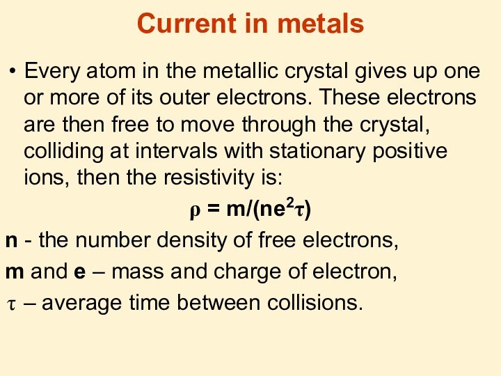
Current in metals
Every atom in the metallic crystal
gives up one or more of its outer electrons.
These electrons are then free to move through the crystal, colliding at intervals with stationary positive ions, then the resistivity is:ρ = m/(ne2τ)
n - the number density of free electrons,
m and e – mass and charge of electron,
– average time between collisions.
Слайд 7
Resistivity
A conductor with current:
Current density:
I – electric current
A
– the cross-sectional area of the conductor
vd – drift
speedE = ρJ
ρ - resistivity
Слайд 8
Conductivity
A current density J and an electric field
E are established in a conductor whenever a potential
difference is maintained across the conductor:σ is conductivity:
σ = 1/ ρ.
Слайд 9
Ohm’s law again
For many materials (including most metals),
the ratio of the current density to the electric
field is a constant σ that is independent of the electric field producing the current:J = σE
Слайд 10
Magnets
A single magnetic pole has never been isolated.
Magnetic poles are always found in pairs.
The direction of
magnetic field is from the North pole to the South pole of a magnet.
Слайд 11
Magnet Poles
Magnet field lines connect unlike poles.
Magnet field
lines repels from like poles.
Слайд 12
Magnet Force
The magnitude FB of the magnetic force
exerted on the particle is proportional to the charge
q and to the speed v of the particle.The magnitude and direction of FB depend on the velocity of the particle and on the magnitude and direction of the magnetic field B.
When a charged particle moves parallel to the magnetic field vector, the magnetic force acting on the particle is zero.
When the particle’s velocity vector makes any angle Θ≠0 with the magnetic field, the magnetic force acts in a direction perpendicular to both v and B.
The magnetic force exerted on a positive charge is in the direction opposite the direction of the magnetic force exerted on a negative charge moving in the same direction.
The magnitude of the magnetic force exerted on the moving particle is proportional to sin Θ, where Θ is the angle the particle’s velocity vector makes with the direction of B.
Слайд 13
The text in the previous slide can be
summarized as:
So the units for B are:
The magnetic force is perpendicular to both v and B.FB=qVBsinΘ
Слайд 14
Direction of FB
Right hand rule:
The fingers point in
the direction of v, with B coming out of
your palm, so that you can curl your fingers in the direction of B. The direction of , and the force on a positive charge, is the direction in which the thumb points.
Слайд 15
Magnetic field direction
Magnetic field lines coming out of
the paper are indicated by dots, representing the tips
of arrows coming outward.Magnetic field lines going into the paper are indicated by crosses, representing the feathers of arrows going inward.
Слайд 16
Magnetic Force on a Current
Magnetic force is exerted
on a single charge moving in a magnetic field.
A current-carrying wire also experiences a force when placed in a magnetic field. This follows from the fact that the current is a collection of many charged particles in motion; hence, the resultant force exerted by the field on the wire is the vector sum of the individual forces exerted on all the charges making up the current. The force exerted on the particles is transmitted to the wire when the particles collide with the atoms making up the wire.Слайд 17 n is the number density of charged particles
q
vd is the drift speed of q
A – area
of the segmentL – the length of the segment
Then AL is the volume of the segment, and
nAL is the number of charged particles q.
Then the net force acting on all moving charges is:
Слайд 18
Arbitrary shaped wire
The force on a small segment
of an arbitrary shaped wire is:
The total force is:
a
and b are the end points of the wire.
Слайд 19
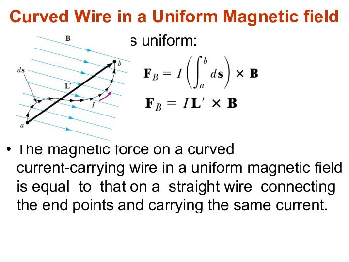
as B is uniform:
The magnetic force on a
curved current-carrying wire in a uniform magnetic field is
equal to that on a straight wire connecting the end points and carrying the same current.Curved Wire in a Uniform Magnetic field
Слайд 20 So, the force on a straight wire in
a uniform magnetic field is:
is a vector multiplication.Where L is a vector that points in the direction of the current I and has a magnitude equal to the length L of the segment. This expression applies only to a straight segment of wire in a uniform magnetic field.
Magnetic force on a straight wire
Слайд 21
Loop Wire in a Uniform Magnetic field
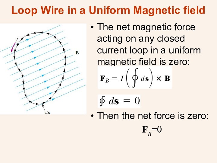
The net
magnetic force acting on any closed current loop in
a uniform magnetic field is zero:Then the net force is zero:
FB=0
Слайд 22
Current Loop Torque in a Uniform Magnetic Field
-
Overhead view of a rectangular loop in a uniform
magnetic field.Sides 1 and 3 are parallel to magnetic field, so only sides 2 and for experiences magnetic forces.
- Magnet forces, acting on sides 2 and 4 create a torque on the loop.
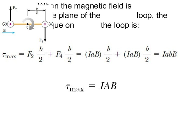
Слайд 23 When the magnetic field is parallel to the
plane of the loop, the maximal torque on the
loop is:ab is the area of the loop A:
Слайд 24 When the loop is not parallel to the
magnetic field, i.e. the angle between A and B
is Θ < 90° then:So the torque on a loop in a uniform magnetic field is:
This formula is correct not only for a rectangular loop, but for a planar loop of any shape.
Слайд 25
In formula for torque
we have vector
A:
- Its direction is perpendicular
to the plane of the loop, - its magnitude is equal to the area of the loop.
We determine the direction of A using the right-hand rule. When you curl the fingers of your right hand in the direction of the current in the loop, your thumb points in the direction of A.
Area Vector
Слайд 26
Right – hand rule for loop
The direction of the
magnetic moment is the same as the direction of
A.
Слайд 27
Magnetic Moment
The vector product IA is defined to
be the magnetic dipole moment μ (often simply called
the “magnetic moment”) of the current loop:Then the torque on a current-carrying loop is:
Слайд 28
Potential Energy of a Magnetic Moment
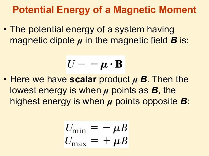
The potential energy
of a system having magnetic dipole μ in the
magnetic field B is:Here we have scalar product μ B. Then the lowest energy is when μ points as B, the highest energy is when μ points opposite B:
Слайд 29 Motion of a Charged Particle in a Uniform
Magnetic Field
When the velocity of a charged particle is
perpendicular to a uniform magnetic field, the particle moves in a circular path in a plane perpendicular to B. The magnetic force FB acting on the charge is always directed toward the center of the circle.
Слайд 31
Lorentz Force
In the presence of E and B,
the force acting on a charged particle is:
here q
is the charge of the particle,v – the speed of the particle,
E – electric field vector
B – magnetic field vector
Слайд 32
The Hall Effect
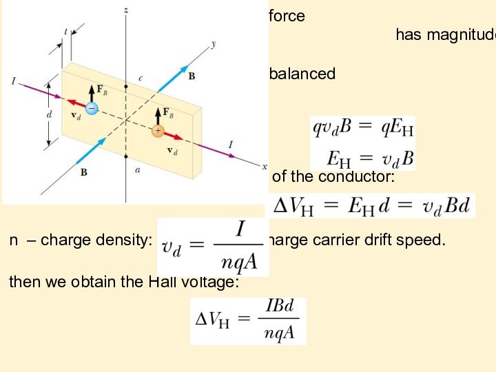
When a current-carrying conductor is placed
in a magnetic field, a potential difference is generated
in a direction perpendicular to both the current and the magnetic field.Слайд 33 the magnetic force
exerted on the carriers
has magnitude qvdB.this force is balanced by the electric force qEH:
d is the width of the conductor:
n – charge density: .vd - charge carrier drift speed.
then we obtain the Hall voltage:
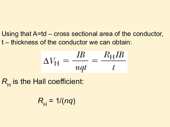
Слайд 34 Using that A=td – cross sectional area of
the conductor,
t – thickness of the conductor we can
obtain:RH is the Hall coefficient:
RH = 1/(nq)
Слайд 35 When the charge carriers in a Hall-effect apparatus
are negative, the upper edge of the conductor becomes
negatively charged, and c is at a lower electric potential than a.When the charge carriers are positive, the upper edge becomes positively charged, and c is at a higher potential than a.
