Слайд 2
Executive Summary
Constraint solvers need contact points to prevent
penetration.
We can use SAT to compute a contact manifold
in one shot.
We can use GJK to build up a contact manifold point-by-point.
Слайд 3
Contact
Contact occurs when two shapes touch.
We model contact
to prevent penetration and to simulate friction.
Modeling contact requires
some geometry and a lot of finesse.
Слайд 4
Contact Manifolds
For convex polyhedra, a contact manifold is
ideally a single point, a line segment, or a
convex polygon.
For general convex 3D shapes, the contact manifold is a convex 2D shape.
Did I mention overlap?
Слайд 5
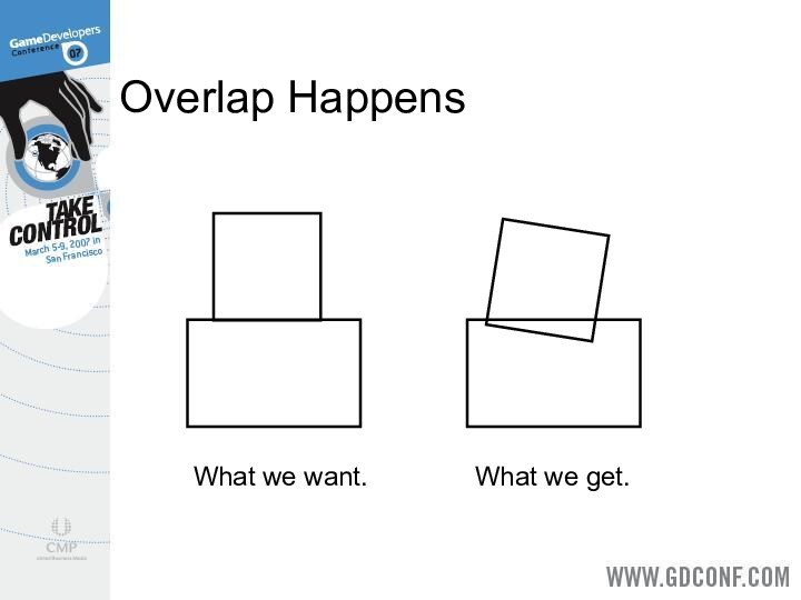
Overlap Happens
What we want.
What we get.
Слайд 6
Approximate Manifolds
We use a collection of contact points
to approximate the contact manifold.
Our goal is fast, stable,
and plausible simulation.
In this sense, computing good manifolds is an art.
Слайд 7
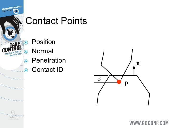
Contact Points
Position
Normal
Penetration
Contact ID
Слайд 8
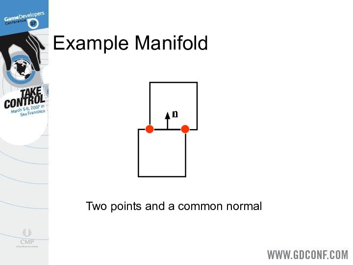
Example Manifold
Two points and a common normal
Слайд 9
Contact Manifold Quality
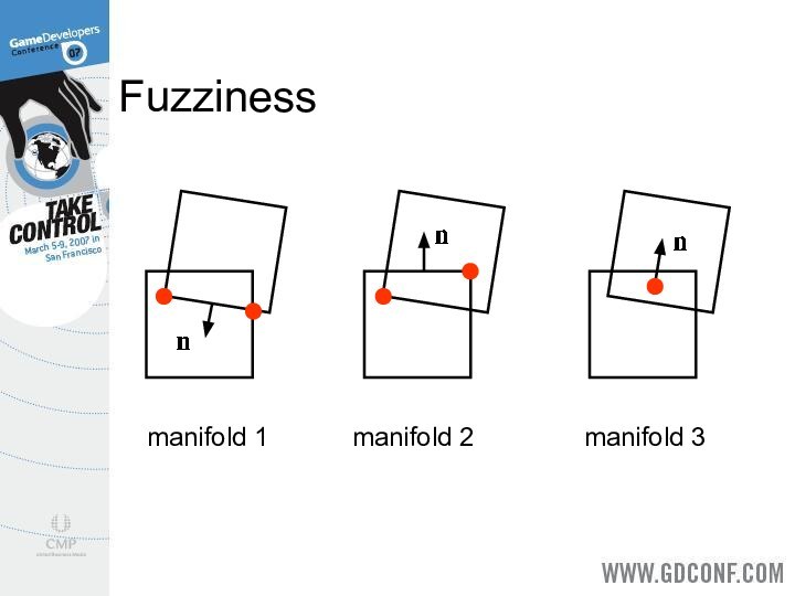
When objects penetrate significantly the contact
manifold is fuzzy.
Contact solvers like coherence.
Be consistent from step-to-step.
Слайд 10
Fuzziness
manifold 1
manifold 2
manifold 3
Слайд 11
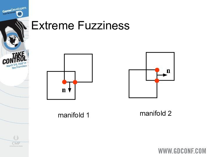
Extreme Fuzziness
manifold 1
manifold 2
Слайд 12
Using the SAT
Mainly useful for convex polyhedra (boxes,
triangles, etc).
Find the axis of minimum penetration.
For edge-edge contact,
find the midpoint.
For face contact, use Sutherland-Hodgeman clipping.
Слайд 13
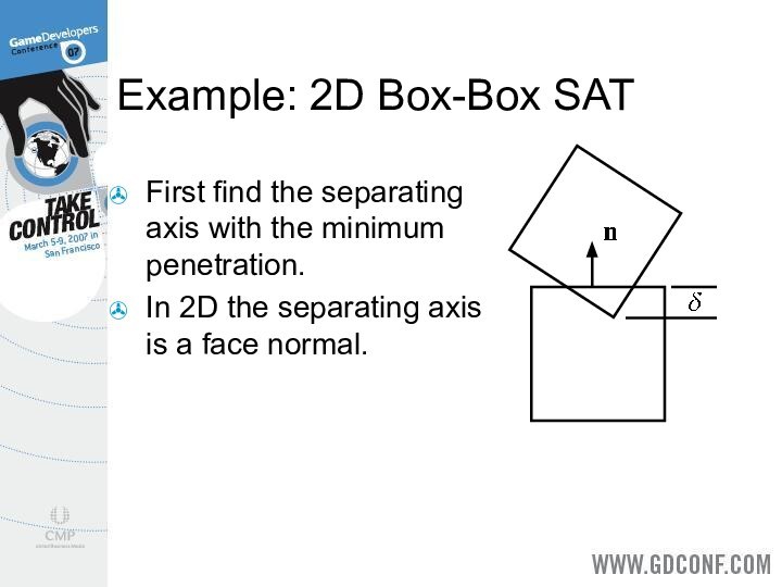
Example: 2D Box-Box SAT
First find the separating axis
with the minimum penetration.
In 2D the separating axis is
a face normal.
Слайд 14
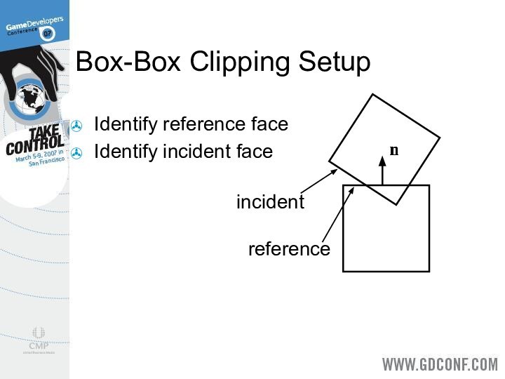
Box-Box Clipping Setup
Identify reference face
Identify incident face
incident
reference
Слайд 15
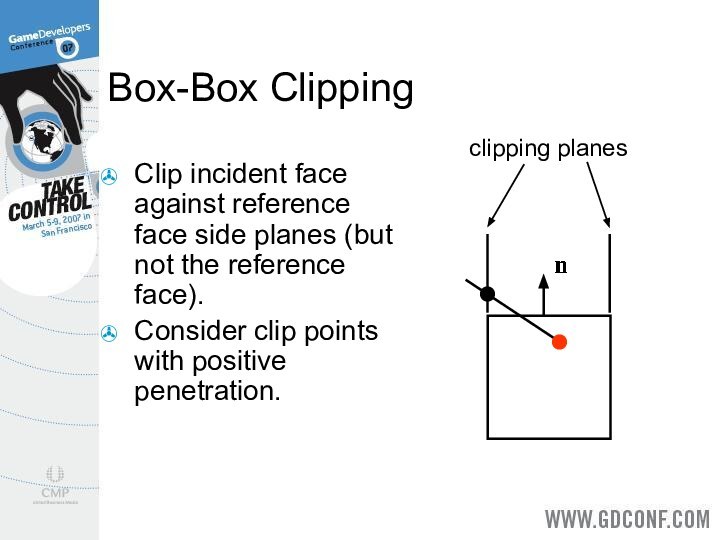
Box-Box Clipping
Clip incident face against reference face side
planes (but not the reference face).
Consider clip points with
positive penetration.
clipping planes
Слайд 16
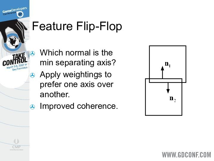
Feature Flip-Flop
Which normal is the min separating axis?
Apply
weightings to prefer one axis over another.
Improved coherence.
Слайд 17
Coherence
Apply old force/impulse solution at the beginning of
the step.
Fewer iterations and greater stability.
We need a way
to match old and new contacts.
Слайд 18
Feature-Based Contact Points
Each contact point is the result
of clipping.
It is the junction of two different edges.
An
edge may come from either box.
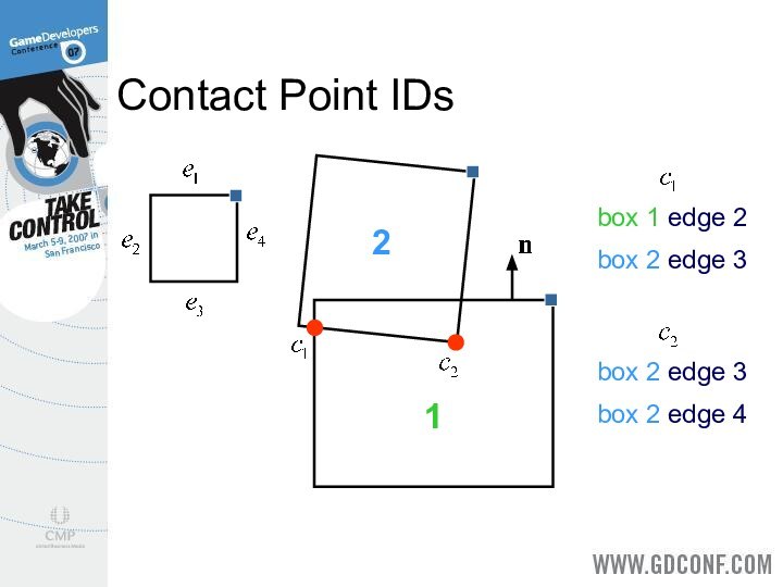
Store the two edge numbers with each contact point – this is the Contact ID.
Слайд 20
GJK Contact Points
Three cases:
- No contact
- Shallow contact
-
Deep contact
Слайд 21
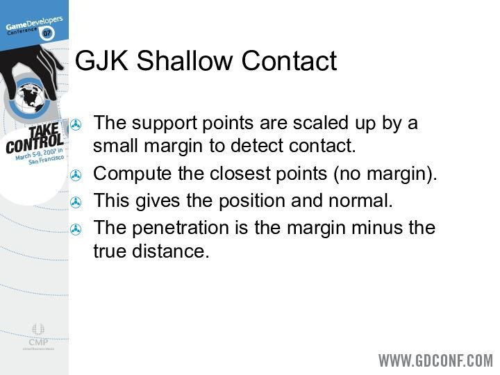
GJK Shallow Contact
The support points are scaled up
by a small margin to detect contact.
Compute the closest
points (no margin).
This gives the position and normal.
The penetration is the margin minus the true distance.
Слайд 22
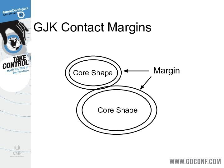
GJK Contact Margins
Core Shape
Margin
Core Shape
Слайд 23
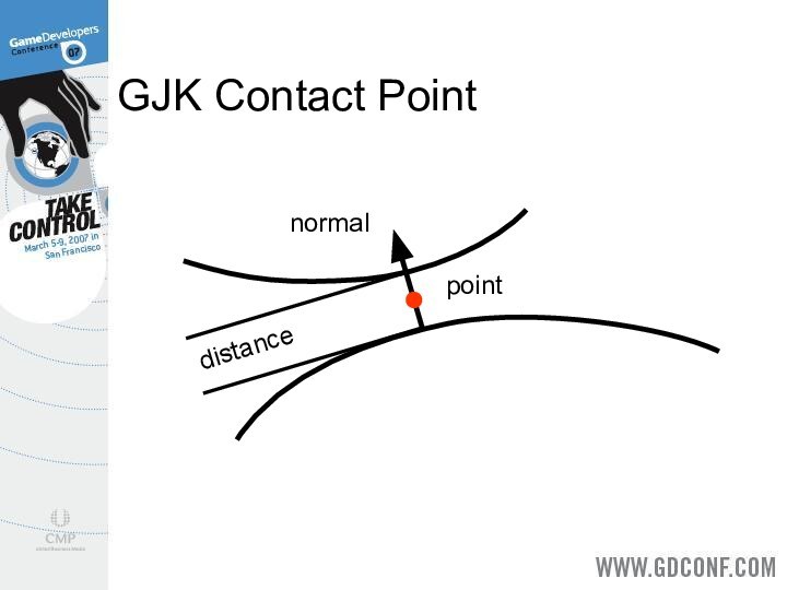
GJK Contact Point
point
normal
distance
Слайд 24
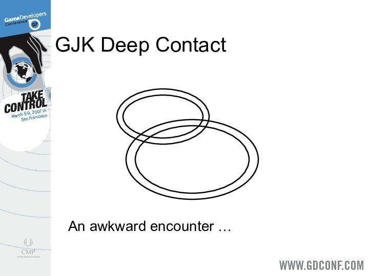
GJK Deep Contact
An awkward encounter …
Слайд 25
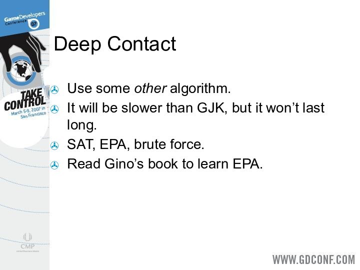
Deep Contact
Use some other algorithm.
It will be slower
than GJK, but it won’t last long.
SAT, EPA, brute
force.
Read Gino’s book to learn EPA.
Слайд 26
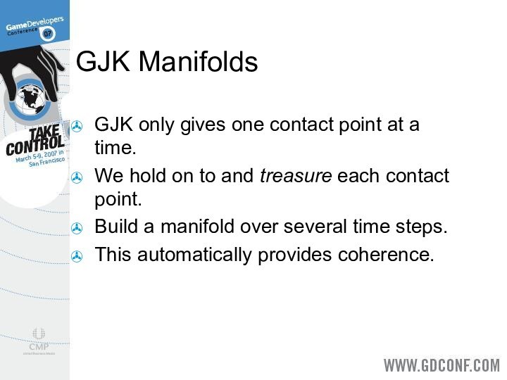
GJK Manifolds
GJK only gives one contact point at
a time.
We hold on to and treasure each contact
point.
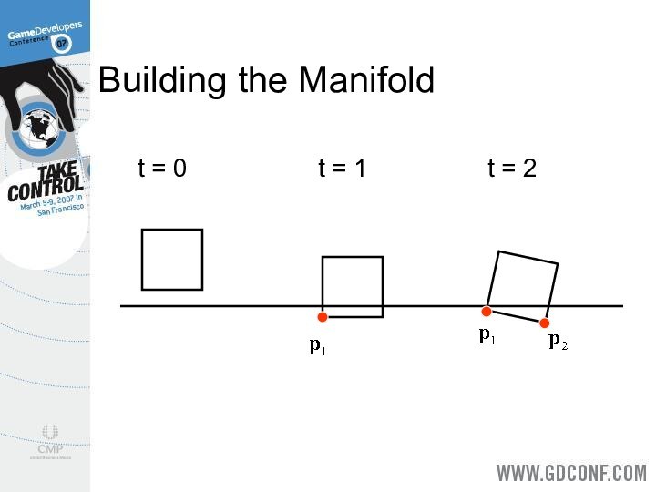
Build a manifold over several time steps.
This automatically provides coherence.
Слайд 27
Building the Manifold
t = 0
t = 1
t =
2
Слайд 28
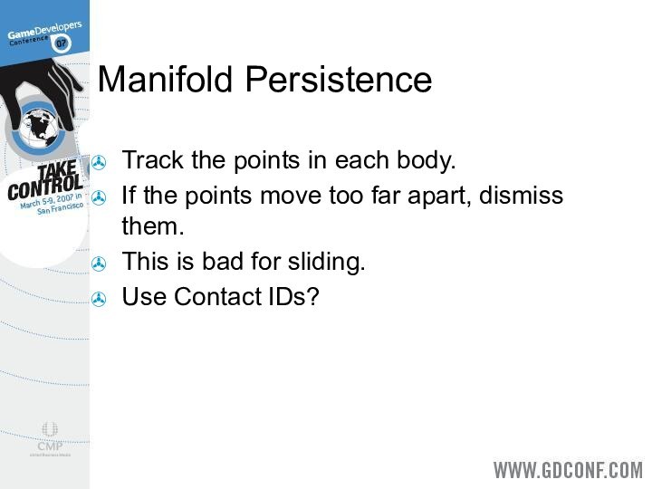
Manifold Persistence
Track the points in each body.
If the
points move too far apart, dismiss them.
This is bad
for sliding.
Use Contact IDs?
Слайд 29
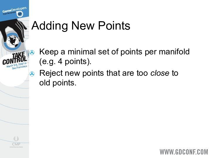
Adding New Points
Keep a minimal set of points
per manifold (e.g. 4 points).
Reject new points that are
too close to old points.
Слайд 30
Manifold Reduction
This applies to one-shot and incremental manifolds.
We
want to keep the minimum number of contact points
for a stable simulation.
This improves performance drastically.
Слайд 31
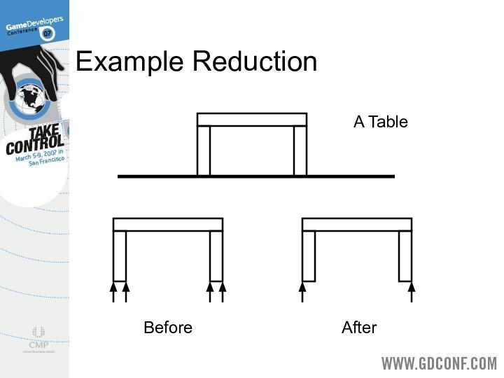
Example Reduction
A Table
Before
After
