- Главная
- Разное
- Бизнес и предпринимательство
- Образование
- Развлечения
- Государство
- Спорт
- Графика
- Культурология
- Еда и кулинария
- Лингвистика
- Религиоведение
- Черчение
- Физкультура
- ИЗО
- Психология
- Социология
- Английский язык
- Астрономия
- Алгебра
- Биология
- География
- Геометрия
- Детские презентации
- Информатика
- История
- Литература
- Маркетинг
- Математика
- Медицина
- Менеджмент
- Музыка
- МХК
- Немецкий язык
- ОБЖ
- Обществознание
- Окружающий мир
- Педагогика
- Русский язык
- Технология
- Физика
- Философия
- Химия
- Шаблоны, картинки для презентаций
- Экология
- Экономика
- Юриспруденция
Что такое findslide.org?
FindSlide.org - это сайт презентаций, докладов, шаблонов в формате PowerPoint.
Обратная связь
Email: Нажмите что бы посмотреть
Презентация на тему по сопромату
Содержание
- 2. It is for building your Prototypes
- 3. using Wireframe to sketch
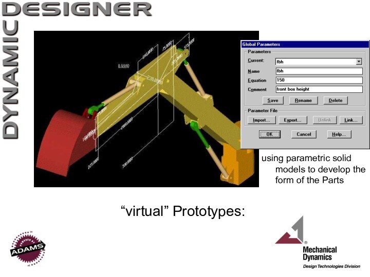
- 4. using parametric solid models to develop the form of the Parts“virtual” Prototypes:
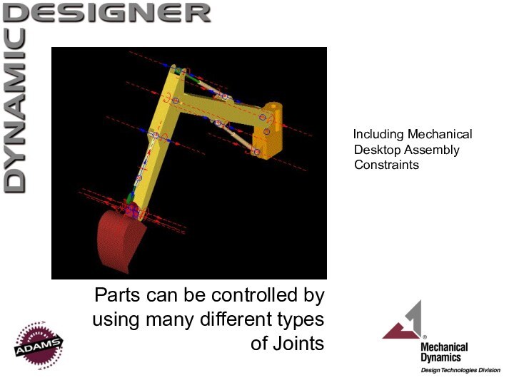
- 5. Parts can be controlled by using many
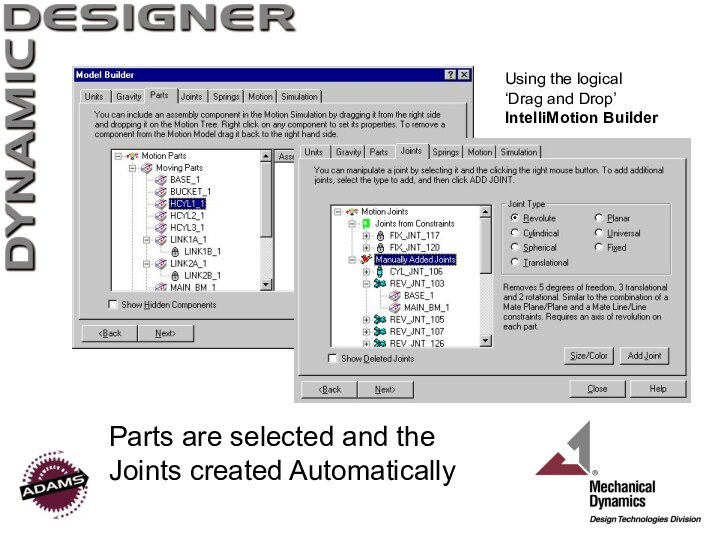
- 6. Parts are selected and the Joints created AutomaticallyUsing the logical ‘Drag and Drop’ IntelliMotion Builder
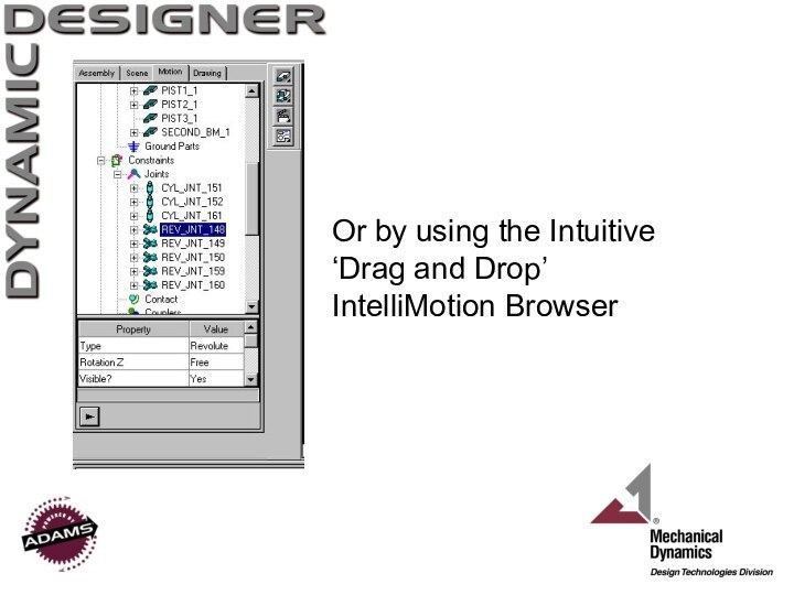
- 7. Or by using the Intuitive ‘Drag and Drop’ IntelliMotion Browser
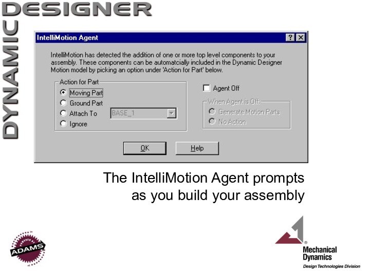
- 8. The IntelliMotion Agent prompts as you build your assembly
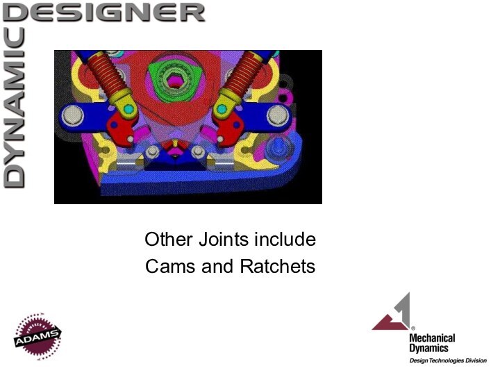
- 9. Other Joints include Cams and Ratchets
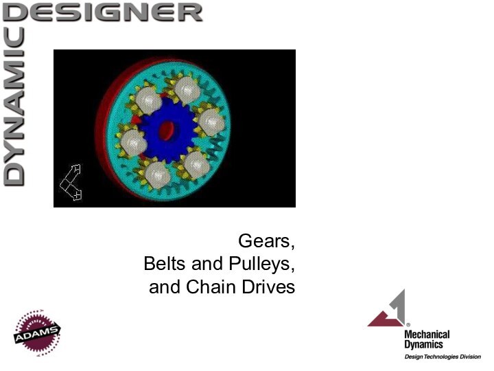
- 10. Gears, Belts and Pulleys, and Chain Drives
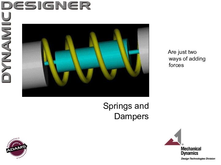
- 11. Springs and Dampers Are just two ways of adding forces
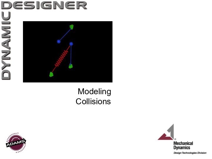
- 12. Modeling Collisions
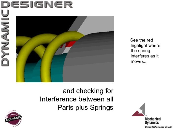
- 13. and checking for Interference between all Parts
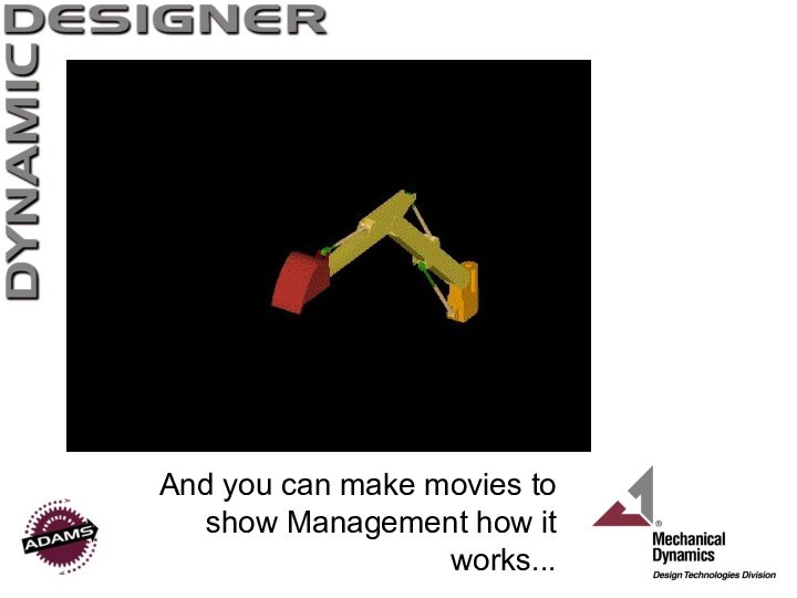
- 14. And you can make movies to show Management how it works...
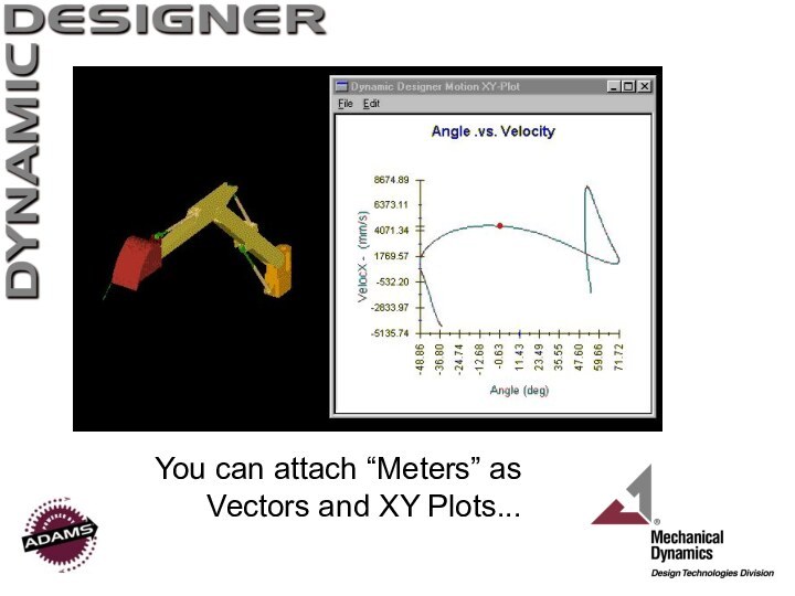
- 15. You can attach “Meters” as Vectors and XY Plots...
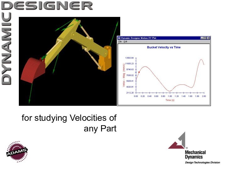
- 16. for studying Velocities of any Part
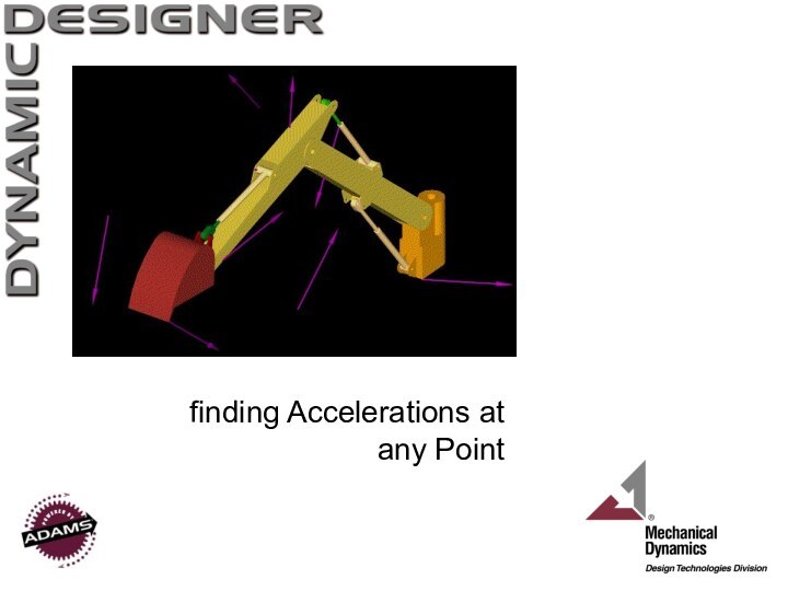
- 17. finding Accelerations at any Point
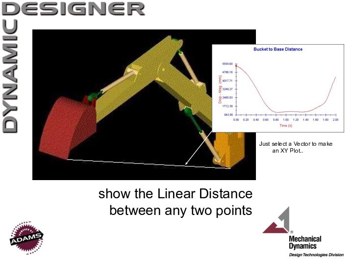
- 18. show the Linear Distance between any two pointsJust select a Vector to make an XY Plot..
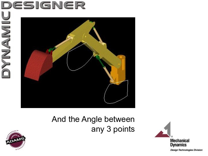
- 19. And the Angle between any 3 points
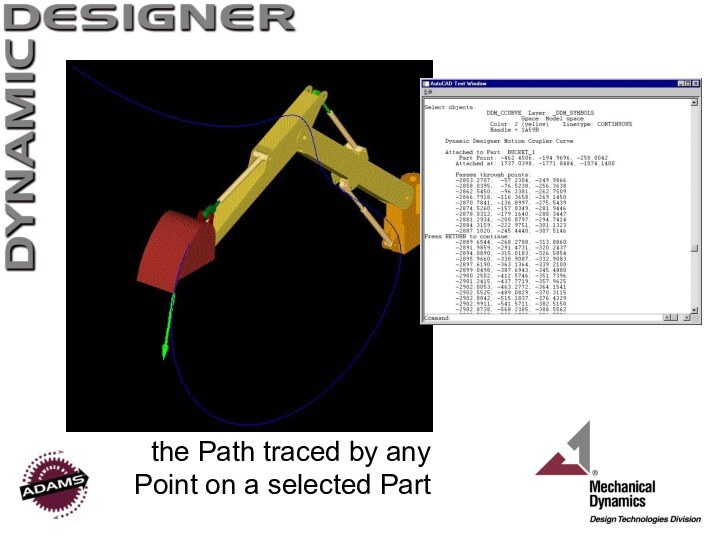
- 20. the Path traced by any Point on a selected Part
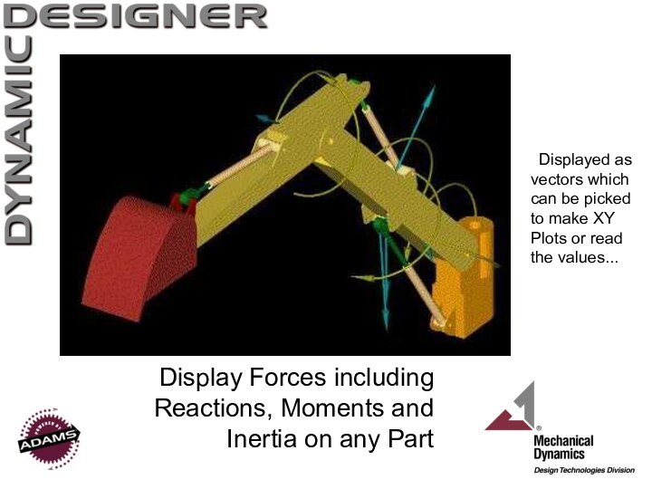
- 21. Display Forces including Reactions, Moments and Inertia
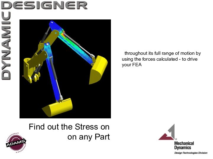
- 22. Find out the Stress on on any
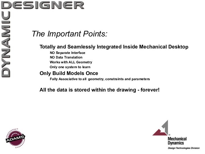
- 23. The Important Points:Totally and Seamlessly Integrated Inside
- 24. Dynamic DesignerGives you the power to go
- 25. Скачать презентацию
- 26. Похожие презентации
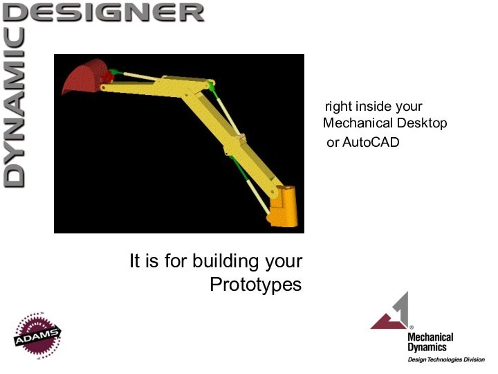
It is for building your Prototypes right inside your Mechanical Desktop or AutoCAD
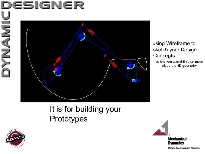
Слайд 3 using Wireframe to sketch your
Design Concepts
before you spend time on more elaborate 3D
geometryIt is for building your Prototypes
Слайд 5 Parts can be controlled by using many different
types of Joints
Including Mechanical Desktop Assembly
Constraints
Слайд 6
Parts are selected and the Joints created Automatically
Using
the logical
‘Drag and Drop’
IntelliMotion Builder
Слайд 13 and checking for Interference between all Parts plus
Springs
See the red highlight where the
spring interferes as it moves...Слайд 21 Display Forces including Reactions, Moments and Inertia on
any Part
Displayed as vectors which can be picked to
make XY Plots or read the values...
Слайд 22
Find out the Stress on on any Part
throughout
its full range of motion by using the forces
calculated - to drive your FEA
Слайд 23
The Important Points:
Totally and Seamlessly Integrated Inside Mechanical
Desktop
NO Separate Interface
NO Data Translation
Works with ALL Geometry
Only one
system to learnOnly Build Models Once
Fully Associative to all geometry, constraints and parameters
All the data is stored within the drawing - forever!
Слайд 24
Dynamic Designer
Gives you the power to go from
what you know, to what you would like to
know… and minimizes engineering assumptions - the most common cause of bad designs!What we call “Dynamics Driven Design”
- or just ‘seeing how it works!’


