- Главная
- Разное
- Бизнес и предпринимательство
- Образование
- Развлечения
- Государство
- Спорт
- Графика
- Культурология
- Еда и кулинария
- Лингвистика
- Религиоведение
- Черчение
- Физкультура
- ИЗО
- Психология
- Социология
- Английский язык
- Астрономия
- Алгебра
- Биология
- География
- Геометрия
- Детские презентации
- Информатика
- История
- Литература
- Маркетинг
- Математика
- Медицина
- Менеджмент
- Музыка
- МХК
- Немецкий язык
- ОБЖ
- Обществознание
- Окружающий мир
- Педагогика
- Русский язык
- Технология
- Физика
- Философия
- Химия
- Шаблоны, картинки для презентаций
- Экология
- Экономика
- Юриспруденция
Что такое findslide.org?
FindSlide.org - это сайт презентаций, докладов, шаблонов в формате PowerPoint.
Обратная связь
Email: Нажмите что бы посмотреть
Презентация на тему по сопромату4
Содержание
- 2. EnhancementsGeometry EnhancementsSTEP CAD InterfaceImproved Semi-Automatic Hex MeshingAttributes
- 3. EnhancementsMSC/NASTRAN Version 70Response Spectrum AnalysisMSC/NASTRAN OP2 Binary
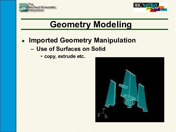
- 4. Geometry ModelingImported Geometry ManipulationUse of Surfaces on Solidcopy, extrude etc.
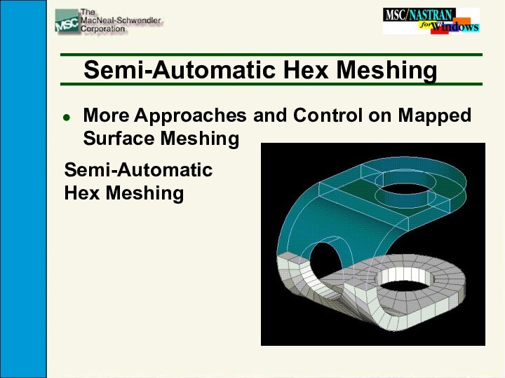
- 5. Semi-Automatic Hex MeshingMore Approaches and Control on Mapped Surface MeshingSemi-Automatic Hex Meshing
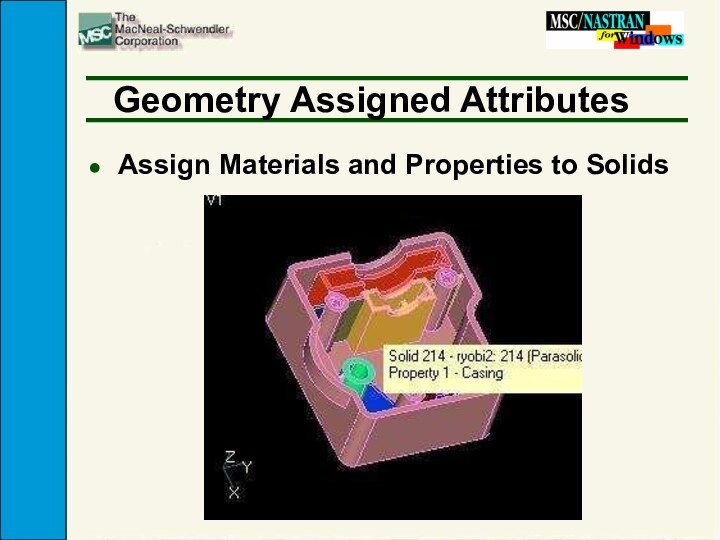
- 6. Geometry Assigned AttributesAssign Materials and Properties to Solids
- 7. General Beam Section CalculatorUses any Surface as
- 8. General Beam Section CalculatorDisplay of Actual Beam Cross-Sections
- 9. Graphics EnhancementsTransparent Solids/Materials/Elements
- 10. Solver EnhancementsKernels TunedNew Compiler5-10% Performance improvementReduced Memory
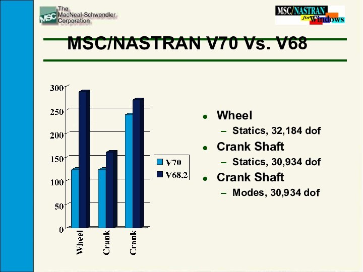
- 11. MSC/NASTRAN V70 Vs. V68WheelStatics, 32,184 dofCrank ShaftStatics, 30,934 dofCrank ShaftModes, 30,934 dof
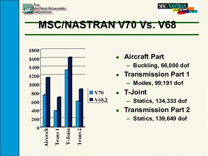
- 12. MSC/NASTRAN V70 Vs. V68Aircraft PartBuckling, 66,000 dofTransmission
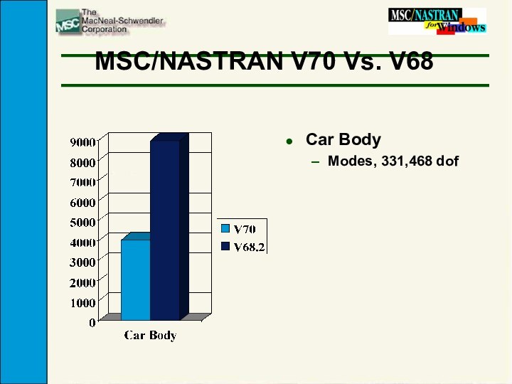
- 13. MSC/NASTRAN V70 Vs. V68Car BodyModes, 331,468 dof
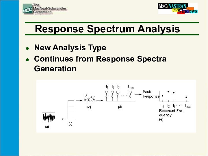
- 14. Response Spectrum AnalysisNew Analysis TypeContinues from Response Spectra Generation
- 15. OUTPUT2 Binary ResultsThe Binary “OP2” File now
- 16. Grid Point Force BalanceGrid Point Force BalancesFree Body Diagrams
- 17. Results Viewing EnhancementsSimultaneous Display of Top and Bottom SurfacesDisplay Shells as Solids
- 18. Scripting LanguageNew Script EditorSupports vb form filesIntegrated
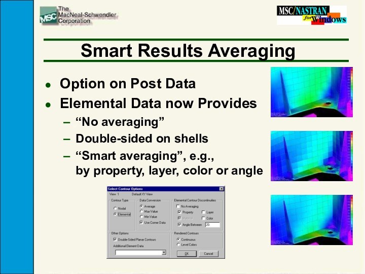
- 19. Smart Results AveragingOption on Post DataElemental Data
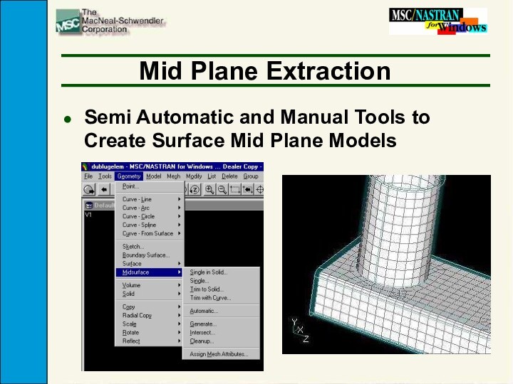
- 20. Mid Plane ExtractionSemi Automatic and Manual Tools to Create Surface Mid Plane Models
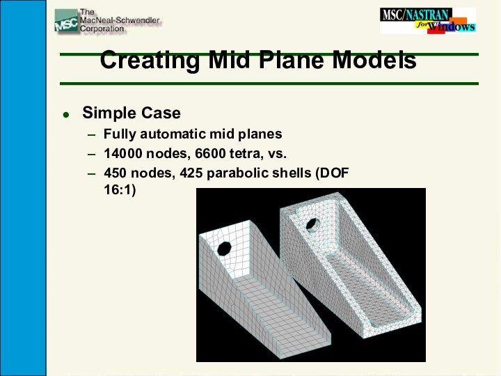
- 21. Creating Mid Plane ModelsSimple CaseFully automatic mid
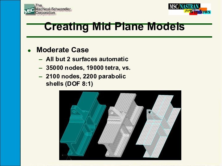
- 22. Creating Mid Plane ModelsModerate CaseAll but 2
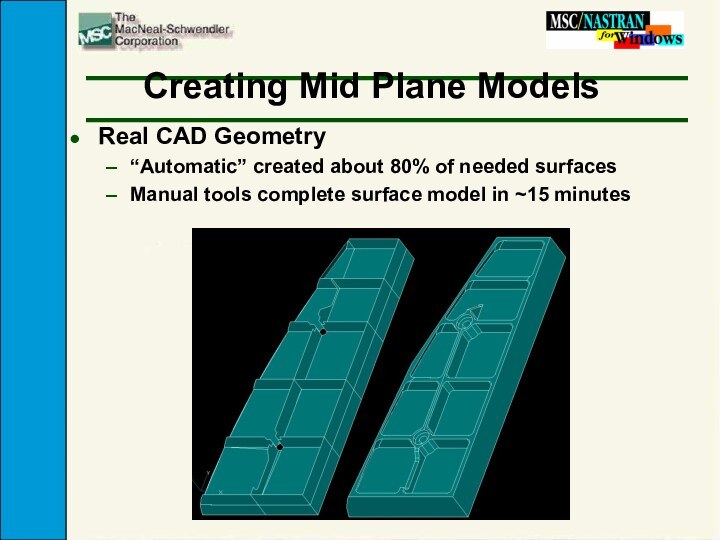
- 23. Creating Mid Plane ModelsReal CAD Geometry“Automatic” created
- 24. Скачать презентацию
- 25. Похожие презентации
EnhancementsGeometry EnhancementsSTEP CAD InterfaceImproved Semi-Automatic Hex MeshingAttributes (Properties, Materials, etc.) Associated with GeometryGeneral Beam Section CalculatorMesh Connection: Zip, Unzip, Link

Слайд 2
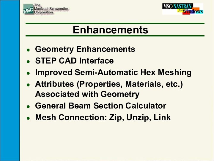
Enhancements
Geometry Enhancements
STEP CAD Interface
Improved Semi-Automatic Hex Meshing
Attributes (Properties,
Materials, etc.) Associated with Geometry
Zip, Unzip, Link
Слайд 3
Enhancements
MSC/NASTRAN Version 70
Response Spectrum Analysis
MSC/NASTRAN OP2 Binary Results
File
Floating Network License
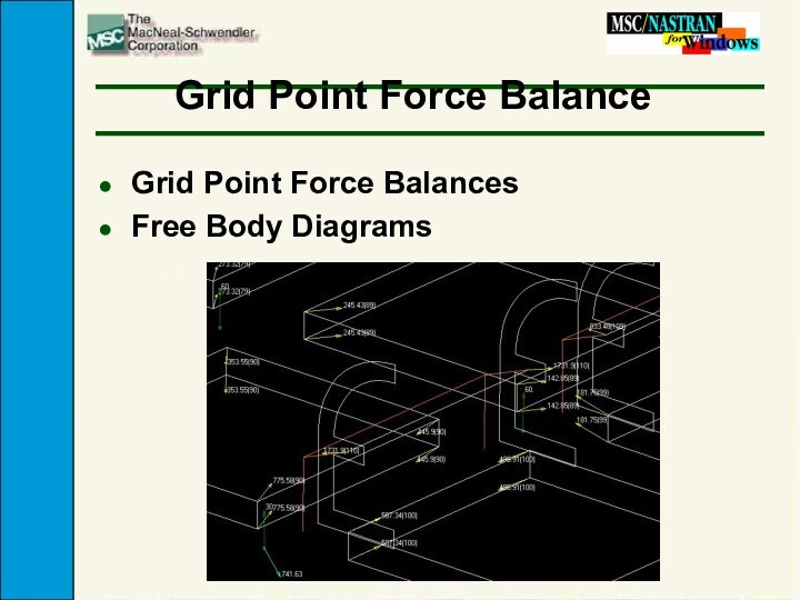
Free Body Diagrams and Grid Point
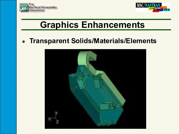
Force BalancesGraphics Enhancements
Scripting Language
Polygon and Freehand Selection
Слайд 5
Semi-Automatic Hex Meshing
More Approaches and Control on Mapped
Surface Meshing
Semi-Automatic Hex Meshing
Слайд 7
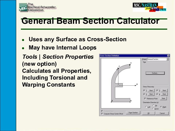
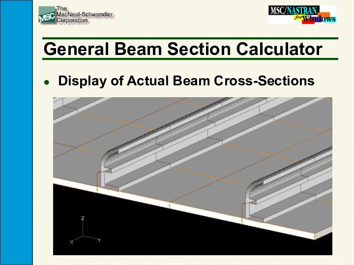
General Beam Section Calculator
Uses any Surface as Cross-Section
May
have Internal Loops
Tools | Section Properties (new option)
Calculates all
Properties, Including Torsional and Warping Constants
Слайд 10
Solver Enhancements
Kernels Tuned
New Compiler
5-10% Performance improvement
Reduced Memory Requirement
less
CPU time for jobs that spill
Iterative Solver
less disk usage
Frequency
Response Enhancements
Слайд 11
MSC/NASTRAN V70 Vs. V68
Wheel
Statics, 32,184 dof
Crank Shaft
Statics, 30,934
dof
Crank Shaft
Modes, 30,934 dof
Слайд 12
MSC/NASTRAN V70 Vs. V68
Aircraft Part
Buckling, 66,000 dof
Transmission Part
1
Modes, 99,191 dof
T-Joint
Statics, 134,333 dof
Transmission Part 2
Statics, 139,649 dof
Слайд 15
OUTPUT2 Binary Results
The Binary “OP2” File now Supported
Compliments
the ASCII Output File (F06)
Over 8X Faster for Large
Results Files
Слайд 17
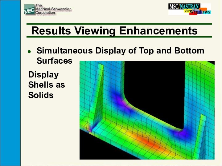
Results Viewing Enhancements
Simultaneous Display of Top and Bottom
Surfaces
Display Shells as Solids
Слайд 18
Scripting Language
New Script Editor
Supports vb form files
Integrated graphical
dialog box designer
Customize Menu Commands
Build your own menus to
run scripts and program filesExtended Functionality
Over 100 new MSC/N4W functions implemented


